Bench Notes
For a few years now, “multizone” in ST’s time-of-flight range has meant an 8 × 8 grid: 64 distances, refreshed up to 15 times a second at full resolution. That’s enough to tell a robot arm that something is on the bench. It won’t tell the arm where the doughnut’s hole is. Sixty-four numbers is a depth map in roughly the way a chessboard is a photograph.
The VL53L9 changes the scale. ST first showed it in February 2024 and started mass production in July 2026. It reports 54 × 42 zones, about 2.3K in all, at up to 100 frames a second, from a reflowable module 12.8 mm long. ST calls it a 3D LiDAR module, and for once the label fits.
Bench Notes is our series on parts and techniques that cross our bench. This first one is, strictly speaking, pre-bench: we haven’t had a VL53L9 on the bench yet. So we’ve set it a simple job on paper. A small robot arm with the sensor on its wrist has to pick up a ring doughnut from a plate without knocking over the coffee cup next to it. What follows is what the arm would see, and what the sensor would ask of the people designing that arm.
From 64 zones to 2,268
The 8 × 8 parts are easy guests. They hang off I²C or SPI, hand over a few kilobytes per frame, and a small microcontroller barely notices them. The VL53L9 behaves more like a small camera that happens to measure distance.
| Spec | VL53L5CX (8 × 8, 2021) | VL53L9 |
|---|---|---|
| Zones | 64 (8 × 8) | 2,268 (54 × 42) |
| Field of view | 45° × 45° (63° diagonal) | 54° × 42° (71° diagonal) |
| Range | up to 4 m | under 5 cm to 8.8 m |
| Frame rate | 60 Hz at 4 × 4, 15 Hz at 8 × 8 | up to 100 Hz at full resolution |
| Data out | I²C, up to 1 MHz | MIPI CSI-2 or I3C |
| Outputs | distance and status per zone | depth, 2D IR with and without illumination, ambient, reflectance, confidence |
| Module size | 6.4 × 3.0 × 1.5 mm | 12.8 × 6.1 × 4.6 mm |
ST’s press release rounds the range up to 9 m; the June 2026 data brief says 8.8 m, so that’s the figure we use. For an arm on a bench, the interesting end of the range is the other one.
How a sensor times light
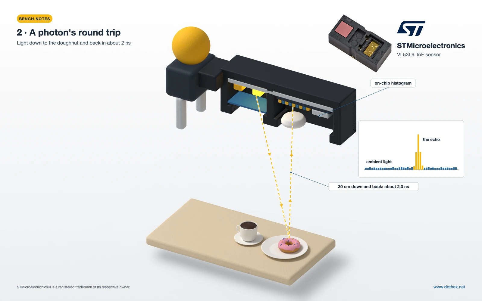
The module fires a short burst of invisible 940 nm light and times how long the echo takes to come back. Light covers about 30 cm per nanosecond, so the top of a doughnut 30 cm below the wrist answers after about 2 ns. Telling 1 cm apart means separating arrival times that differ by about 67 picoseconds.
One pulse can’t do that reliably. The receiver is an array of single-photon avalanche diodes (SPADs), which trigger on individual photons, including stray ones from the lab lights. So the sensor fires many pulses per frame and drops every detected photon into a time bin. Ambient light spreads thinly across the bins, while the real echo piles up in one. The peak of that histogram is the distance.
On the VL53L9, two VCSELs flood the whole scene at once. ST says this avoids the motion artefacts of scanning a dot pattern and helps with small objects and edges. Metasurface optics on both sides shape the light into a rectangular field, and the histogram processing, including compensation for cover-glass crosstalk, runs on the module.
What the arm sees
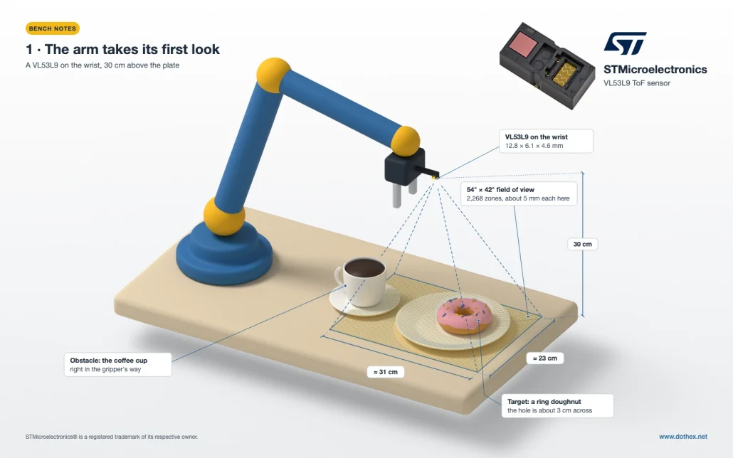
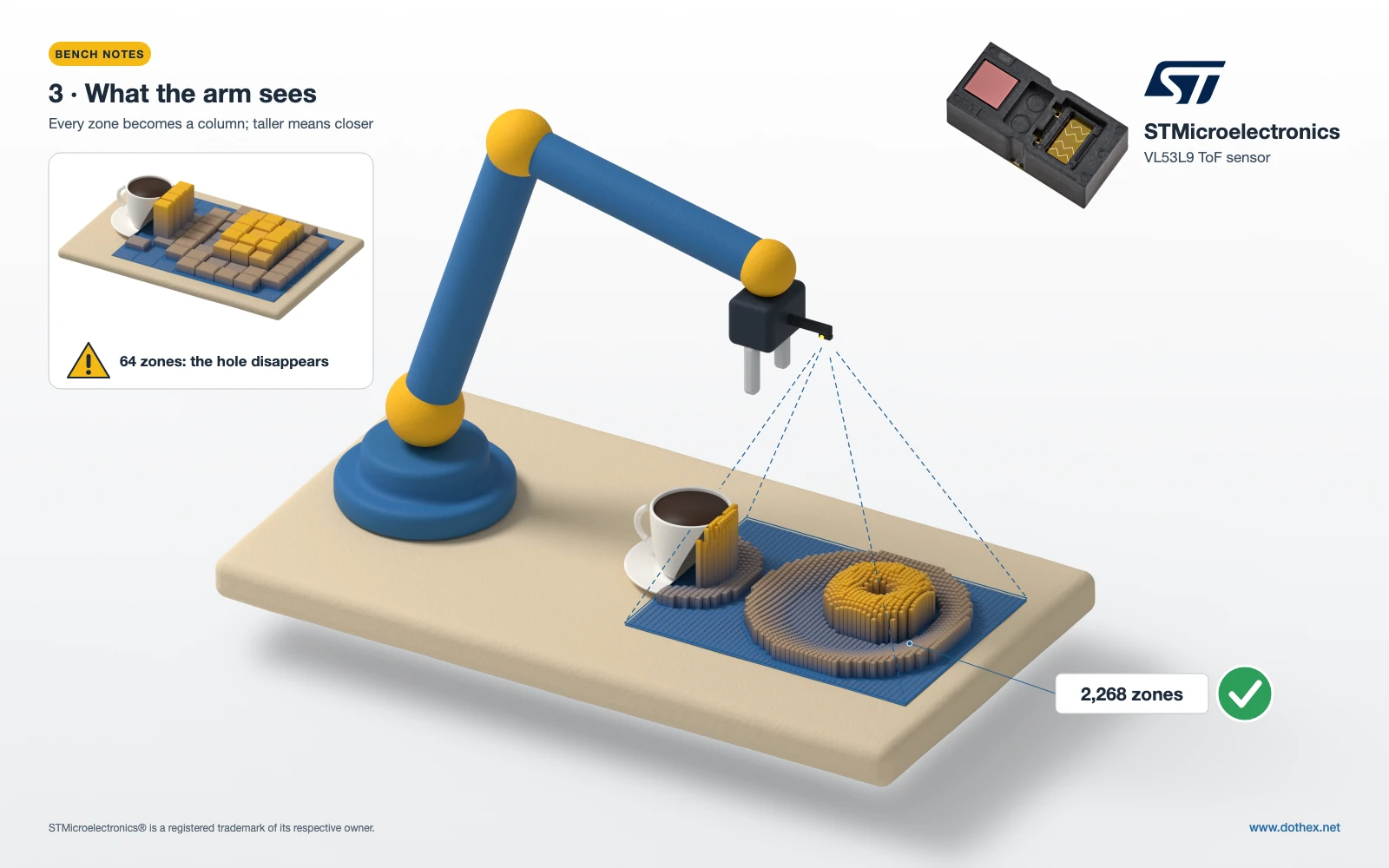
Put the wrist 30 cm above the plate and the sensor’s view covers an area of roughly 31 × 23 cm: the plate, the doughnut and the edge of the coffee cup. Each zone spans about 1°, which at that distance is about 5 mm. A ring doughnut’s hole, at 2–3 cm across, takes up several zones, so it appears in the depth map as a far patch inside a ring of near ones. The arm knows where the hole is and how tall the doughnut stands above the plate.
Run the same scene through an 8 × 8 sensor and each zone is close to 3 cm across. The hole fits inside a single zone and gets averaged away, along with the plate’s rim.
The cup is the obstacle. Its rim and handle show up as a separate shape standing taller than the plate, which is all a motion planner needs to keep the gripper clear of it. We’d leave the coffee itself alone: a liquid surface is not something we’d trust a time-of-flight reading on without testing.
Speed matters on the way down. At 100 frames a second, a gripper closing in at 10 cm/s moves 1 mm between frames, and because the sensor measures from under 5 cm, it keeps reporting as the fingers close round the doughnut. The same depth map would also notice a hand reaching into the workspace, which is a reasonable cue to slow the arm. It isn’t a certified safety function, though; a collaborative arm still needs certified safety sensors for that.
Firmware notes: the data pipe picks your platform
Start with napkin maths. If depth were the only thing on the wire, at 16 bits per zone, one frame would be about 4.5 kB, and 100 frames a second around 3.6 Mbit/s. That looks comfortable for I3C. ST’s own evaluation software says otherwise: an STM32H563 reading the sensor over I3C tops out at 30 frames a second at full resolution, and ST points you to MIPI for the full 100. Real frames carry more than bare depth, and every bus has overhead.
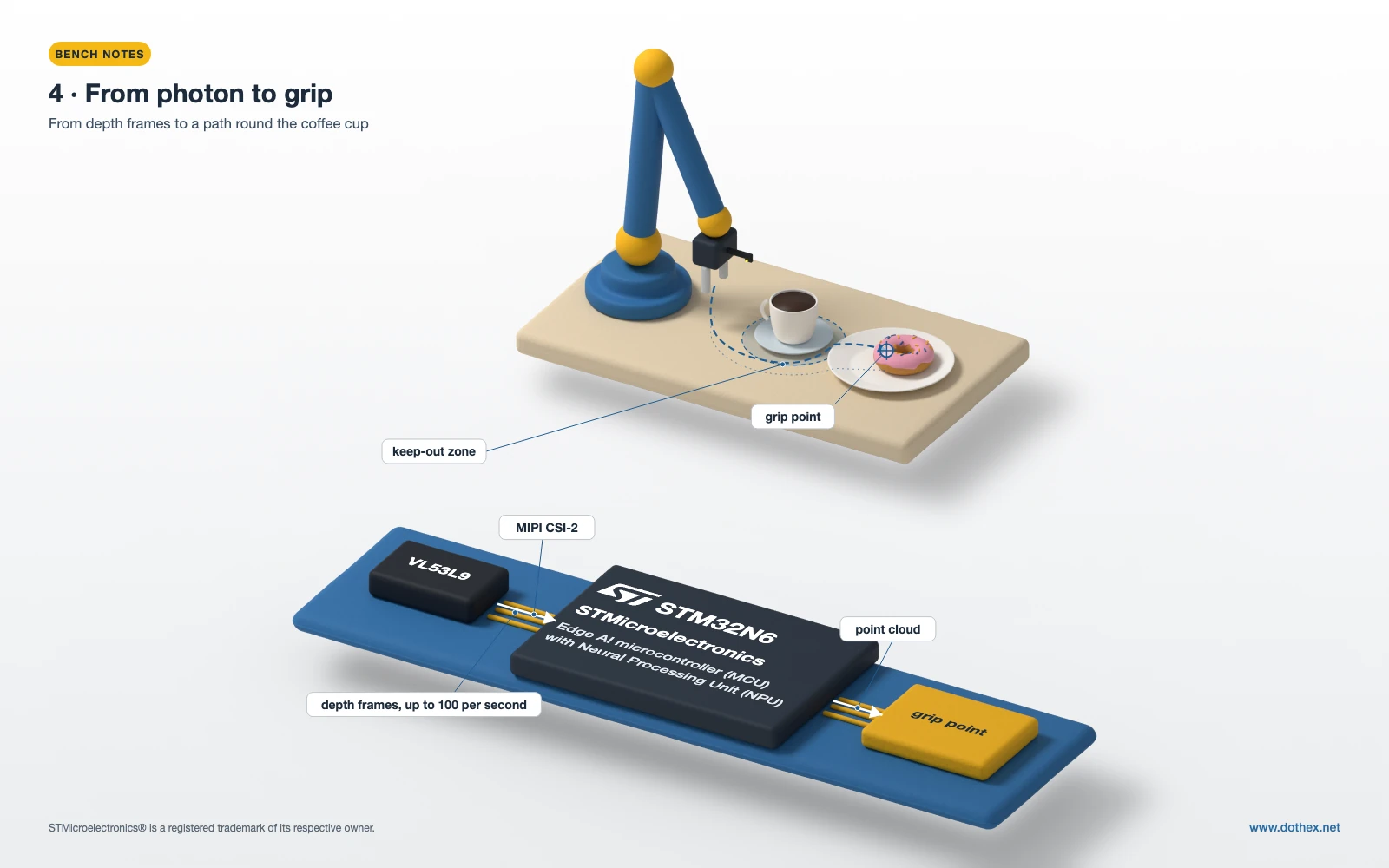
So the platform decision comes early. For a slow pick-and-place arm, 30 fps over I3C may be plenty, and ST’s X-NUCLEO-53L9A1 shield on a NUCLEO-H563ZI is the reference for that route. For the full rate you need a host with a MIPI CSI-2 receiver; ST’s STEVAL-VL53L9 breakout connects by flex cable to STM32N6 boards, Raspberry Pi and Rockchip platforms. The STM32N6 is the interesting one here. It takes CSI-2 in and has a neural processing unit on the same chip, so the depth and 2D IR frames can feed a small model that picks the grip point, without a Linux board in the loop. That’s the kind of design our edge AI work keeps coming back to.
Each zone looks in a fixed direction, so turning a depth frame into a point cloud takes a table of per-zone direction vectors, calculated once at start-up from ST’s documented angles. From there it can feed a ROS 2 planner like any other depth sensor, which is where our robotics work with ROS 2 comes in.
A few habits carry over from camera pipelines. Budget at least two frame buffers and DMA into them, because frames arrive whether you’re ready or not. Measure the CPU time of ST’s post-processing library before promising anyone 100 fps plus a planner. Filter on the confidence map, since dark or steeply angled surfaces return few photons. And record raw frames from every test, so you can replay the awkward grasp instead of trying to recreate it.
Hardware notes: rails, lanes and the window
The data brief shows VBAT at 2.8–4.8 V, AVDD at 2.8 or 3.3 V, DVDD at 1.2 V and IOVDD at 1.2 or 1.8 V. There’s no 3.3 V logic option, so a 3.3 V host needs level translation, and for I3C the translator has to handle push-pull signalling at speed. Settle that before layout.
On a wrist, the cable matters as much as the board. Treat the MIPI lanes like a camera’s: controlled-impedance differential pairs, short and length-matched (ST’s breakout schematic calls for 50 Ω single-ended and 100 Ω differential), and a flex that survives the joint moving thousands of times a day. XSHUT, INTR and SYNC_IN all appear on the application schematic. If SYNC_IN does what its name suggests, it will let you line up depth frames with a camera on the same wrist.
Put your real cover window in front of an evaluation board early, and test the last few centimetres of the approach with it in place. At 4.6 mm tall, the module is roughly three times the height of the VL53L5CX, which matters when it sits beside a gripper. ST quotes 150 mW typical system power, small next to the arm’s motors. The module is certified Class 1 and runs its own laser-safety checks, but the product still needs its own compliance file.
What we’d check first on the evaluation kit
- The real frame rate over the interface we’d ship, with our own processing running.
- Whether the doughnut’s hole and the cup’s rim come out cleanly at 20–40 cm.
- Readings over the last 5 cm of the approach, behind our actual cover window.
- Depth noise on dark and shiny objects, such as a black mug or a foil wrapper.
- Behaviour under the bench lights we’d actually use.
- Interference from a second VL53L9 on a second arm.
A sensor like this sits between firmware and optics, and most of the surprises come from the gap between them. If you’re working out how a robot, an arm or any other machine should see the space around it, our sensors and algorithms work is a good place to start, or talk to an engineer →
Sources: ST’s VL53L9CX product page and data brief DB5499 (Rev 5, June 2026); ST’s VL53L9 blog post and press release of 22 June 2026; STSW-IMG052 for the I3C frame-rate note; the STEVAL-VL53L9 data brief; the VL53L5CX product page and datasheet DS13754.